|
The OSMC is a high-power H-bridge circuit designed to control permanent magnet DC motors.
It was designed expressly as a motor control for robot combat in competitions such as
BattleBots™ and the like. However the attributes
of a controller for such an environment are suitable for a wide range of
commercial or industrial motor control applications. The OSMC can drive a wide variety of
motors and other loads and is easy to mount and interface to a variety of microcontroller units.
The low-cost OSMC is also easy to modify or repair if needed. |

Click for larger image |
The OSMC power unit has the following specifications and features:
| Supply voltage |
13V to 50V (36V max battery rating) |
| Output Current (continuous) |
160A |
| Output Current (surge) |
>400A |
| Weight |
0.6 lb |
| MOSFETs |
16 ea. IRFB3207 (or IRF1405 on older units) |
| On Resistance |
.0026 ohm max at 25C |
| Cooling |
40 CFM fan |
| Bridge Driver |
Intersil HIP4081A |
| Logic Interface |
10-pin dual-row header |
| RC Interface |
External via logic interface |
| Power Supply |
12V .5A regulator |
| Current Limiting |
Optional Add-on |
| Connectors |
Solder pads for up to 10 ga wire or #8 bolts |

Click for larger image |
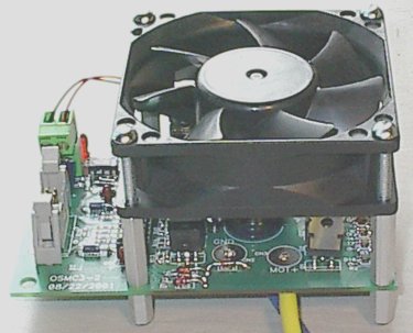
Unlike most motor controls the OSMC
does not use a heavy heatsink to extract heat from
the MOSFETs. Rather, it uses a cooling fan to blow air across the board. This removes
heat more quickly than a plate type heatsink and has lower weight. The fan itself is
a commonly available 80mm square computer cooling fan. Either a 12V or 24V fan may be
installed on the OSMC. Mounting holes are provided at the correct spacing to mount the
fan directly over the MOSFETs for maximum cooling efficiency. |
The OSMC is a simple H-bridge power amplifier. It does not have any on-board logic to
interpret RC or other commands. An external logic interface is required to translate
command inputs into the PWM signals needed to drive the board. This increases system complexity
somewhat but also increases flexibility as the OSMC board may be driven by any microcontroller
or other signal source that can provide PWM and Enable logic.
|
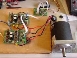
One of the major advantages of separating the power section of the controller from the logic
interface section is to allow the power units to be paralleled for special applications. One
exciting application of this is to use two OSMC boards on a single interface channel to control high-powered
four-brush motors such as the RobotBooks.com MagmotorTM or AstroflightTM motors. By using a special interface cable
the OSMC can control these 4-brush motors at twice the current of a single power unit. That gives
a continuous current capability of over 300A! The image to the right shows a µMOB controlling
2 OSMC boards driving a four inch Magmotor. Stall testing with this motor and 24V of Hawker batteries showed
no appreciable heating of the OSMC boards.
Another option for this method of driving two OSMC power units from one RC interface channel
is to drive a slaved pair of motors from each channel. This allows 4-wheel drive robots to run a slaved pair of
motors on each side of the robots with only a single RC interface. In fact, this method has been successfully
used with three OSMC boards per channel for a six-wheel drive robot.
|
Click for larger image |
Robot Power offers the OSMC in fully assembled units, various kit forms, and as a bare
circuit board. Check the Web store for details on prices and
special offers.